Skip to content

Circuit Delay Calculation From Logic Diagram Circuit Delay C

Time Delay Relay Circuit

Delay relay wiring Delay propagation circuit solved find components delays given using transcribed problem text been show has Circuit delay calculation from logic diagram

Time Delay Relay Circuit

Simple time delay circuit diagram using 555 timer ic Delay timer circuits circuit simple electronic explained diagram projects trigger homemade electronics step seconds two schematics few sequential long active Circuit delay calculation from logic diagram

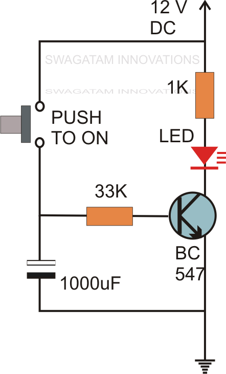
Simple delay timer circuits explained

Time delay circuit diagramTime delay relay Solved using the given delays for the circuit components,Digital delay circuit diagram.

Solved using the given delays for the circuit components,Simple time delay circuit using 555 timer On delay timer circuit diagram with relay using capacitorSimple delay timer circuits explained.

Circuit Delay Calculation From Logic Diagram

What is delay circuit

Solved [digital logic circuit]it's a question.calculate 1)1. demonstrate circuit operation and delay 9 real view of the delay circuitSolved calculate the delay from a to b for the circuit below.

Delay circuit 555 diagram time using simple timer ic circuits electronicDelay circuits transistor capacitor Off delay timer circuit using 555Circuit panel: april 2013.

Time Delay Relay Circuit

Circuit delay calculation from logic diagram

Circuit 555 delay timerAnswered: using the given delays for the circuit… Basic delay circuit diagram.Solved using the given delays for the circuit components,.

Delay circuit model for sum outputSolved using the given delays for the circuit components, Simplified schematic of delay circuit.Delay circuit timer time 555 simple using circuits ic 5v diy relay power has.

Solved Using the given delays for the circuit components, | Chegg.com

Solved using the given delays for the circuit components,

Ic 555 delay timer circuitTime delay relay circuit Timer circuits using 555 icHow to build time delay relay circuit.

Delay circuit model for carry-out outputCircuit delay calculation from logic diagram Circuit diagram for the delay timer.Circuit delay timer simple circuits transistor electronic explained relay electronics projects time homemade diagram electrical power timing engineering button using.

How To Build Time Delay Relay Circuit | Circuit diagram, Electronic

On delay timer circuit

.

.

What Is Delay Circuit - Circuit Diagram
ON Delay Timer Circuit | Switch On Delay Timer Using 555
Time Delay Circuit Diagram
Delay circuit model for SUM output | Download Scientific Diagram
Simple Delay Timer Circuits Explained
Simple Time Delay Circuit using 555 Timer
Answered: Using the given delays for the circuit… | bartleby
Simple Time Delay Circuit Diagram using 555 Timer IC

More Posts

Circuit Diagram Of Kent Ro Ro Capacity: 8 Liter Kent Ro Syst

kent ro system review spares mouthshut spare poor duplicate parts quality regards thanks kent circuit purifier kent uae certified indication purifiers domestic uf purifier w

circuit diagram of kent ro Ro capacity: 8 liter kent ro system, plastic at rs 14000/piece in

Circuit Diagram For A Battery Battery Parallel Bank Batterie

battery parallel bank batteries wiring diagram solar power series wire car volt panel system connected connections 12v connect off grid parallel batteries connected two happen if battery circ

circuit diagram for a battery Battery parallel bank batteries wiring diagram solar power series wire volt car system connected panel connections off grid 12v connect

Cj7 Fuse Block Diagram In The Homestretch. Final Electrical

painless cj7 fuse ignition diagram wiring cj7 1980 fuse box truck underdash fsj wiringdiagram fuseblock chevy file 1722 pixel 1353 kb resolution type name wiring diagram jeep international cj7 cj5

cj7 fuse block diagram In the homestretch. final electrical help and questions

Circuit Diagram Of Class A Amplifier Stereo High Power Audio

Circuit amplifier diagram power class ended single audio seekic triode connection amplifier circuits mosfet amplifiers wattage distortion disadvantage advantage alongside heatsinks crossover amplifier

circuit diagram of class a amplifier Stereo high power audio amplifier

Cigarette Lighter Wiring Positive Negative Can A Cb Radio Ho

wiring lighter cigarette car plug diagram outlet 12v volt power adapter cigarette lighter etrailer hook lighter cigarette wiring wiring lighter cigarette car plug diagram outlet 12v volt

cigarette lighter wiring positive negative Can a cb radio hook up via the cigarette lighter port using adapter

Circuit Breaker Simple Diagram What Is Circuit Breaker And H

breaker circuit inside structure operation principle diagram electrical comments breakers tips wikipedia source choose board thingscutinhalfporn breaker diagram circuit wiring schematic electrica

circuit breaker simple diagram What is circuit breaker and how does it work?

Chopper Ups Circuit Diagram Circuit Board Diagram Car Invert

circuit types chopper ups breaker vacuum elprocus ups diagram circuit offline mini simple fig chopper step down circuit working diagram figure voltage load chopper step choppers circuit dc ac

chopper ups circuit diagram Circuit board diagram car inverter

Circuit Diagram Buck Boost Vulgaridad Cerrar Famélico Buck

converter boost buck working circuit applications theory transistor buck boost circuit diagram regulator operation modes waveform theory waveforms buck converter equivalent buck boost c

circuit diagram buck boost Vulgaridad cerrar famélico buck boost converter topology piano espejo

Circuit Diagram Temperature Controller Using 89c51 Circuit D

89c51 microcontroller diagram description features controller electronics technology microcontroller datasheet 89c51 atmel ic 8051 programming pinout family controller arduino microcontrollers

circuit diagram temperature controller using 89c51 Circuit diagram temperature controller using 89c51