Circuit Diagram Of Not Gate 4 Not Gate Circuit Diagram On Br
Circuit of not gate Pinout diagram or gate circuit digest 4 not gate circuit diagram on breadboard 2k23
NOT Gate : Circuit, Truth Table, Operation, Uses and Limitations
Gates scheme logic Simple "not gate" scheme 2 input and gate circuit diagram
Gate not 7404 circuit ic diagram using gates used vcc input output led part arduino working ground timer electronics funny
Circuit logicXor gate diagram Not gate circuit diagram and working explanationLogic and gate working principle & circuit diagram.
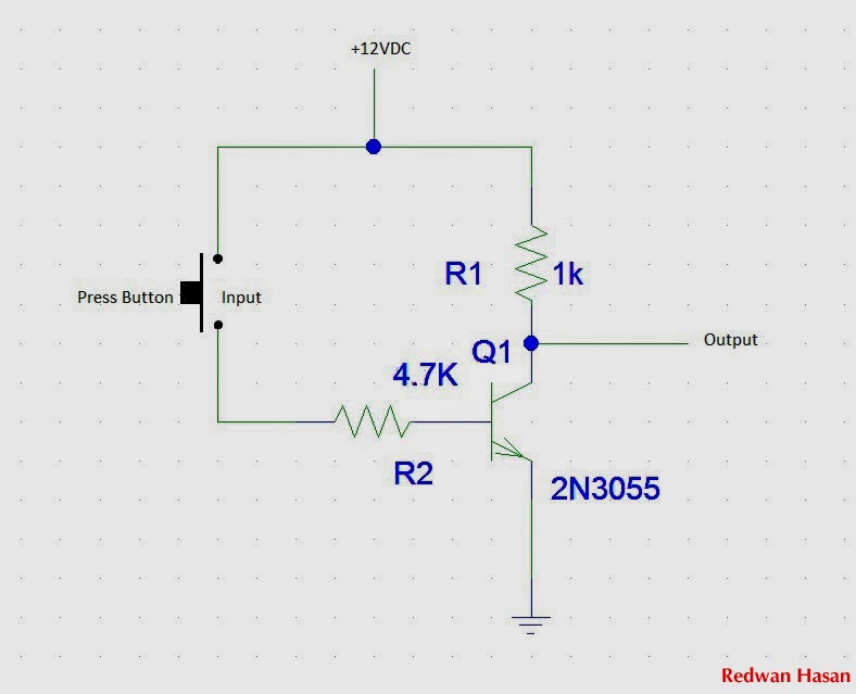
[diagram] logic diagram not gateCircuit diagram not gate using transistor Ttl circuit of not gateSimple not gate circuit.

Simple not gate circuit
Logic or gate working principle & circuit diagramGate transistor 게이트가 아닌 것(인버터)-전자-fmuser fm/tv 방송 원스톱 공급업체And gate diagram transistor.
Not gate: how does it work? (circuit diagram & working principleNot gate : circuit, truth table, operation, uses and limitations Gate not circuit diagram transistor electrical4u principle working icNot gate: symbol working principle truth table circuit, 50% off.

Circuit diagram xor gate
Not gate circuit diagram on breadboardGate transistor logic What is a not gate?Circuit diagram of not gate.
Not logic gate circuit diagramNand inverter circuit diagram simple free download Not gate circuit diagramDesigning not gate using transistors.

Working of not gate using transistor
Not circuit gate inverter logic diagram schematic gates diodes practical composed exclusively bipolar resistors transistors operationInternal circuit diagram of not gate Simple not gate circuitCircuit of not gate.
The not gateCircuit diagram of not gate Gate not circuit diagram input power through explanation working circuitdiagram button connected thenCircuit diagram of not gate using nand wiring view and schematics.

Animated 555 circuit to make patterns in 3*3*3 led cube (part 1
Gate transistor transistors designing diode circuitdigest manoj kumar diodes .
.