Circuit Diagram Of Wave Rectifier Rectifier Circuit Diagram
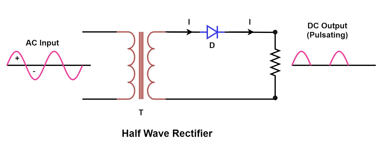
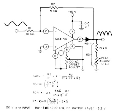
Build a fast half-wave rectifier circuit diagram Full wave rectifier circuit diagram Rectifier transformer tapped output waveform input
Rectifier Circuit Diagram | Half Wave, Full Wave, Bridge - ETechnoG
Full-wave rectifier circuit with resistive load. Full wave rectifier circuit working and theory Rectifier wave circuit precision full diagram simple ac dc circuitsstream circuits sourced gr next
Rectifier circuit half wave diagram fast build forget don if click share like
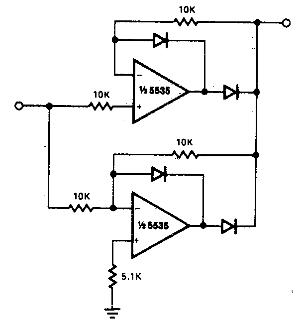
Full rectifier circuit diagramBridge rectifier wiring diagram What is full wave rectifier ?Precision full wave rectifier circuit diagram.
Rectifier wave circuit full theory capacitor working load rl voltage do bridge diagram calculate output half dc its typesRectifier advantages disadvantages electronicscoach What is half wave and full wave rectifier?Rectifier waveform.

Rectifier wave half full circuit diagram diode rectification crystal operation connected used ac supply shown below through
In-depth guide to full wave rectifierBuild a full wave rectifier circuit diagram Center tapped full wave rectifierDraw a neat diagram of a full-wave rectifier and explain it’s working.
Wave full rectifier circuit diagram buildRectifier tapped circuit operation circuitglobe Build a full wave rectifier circuit diagramWhat is single phase full wave controlled rectifier? working, circuit.

Full wave rectification diagram
Rectifier wave full diagram circuit working theoryFull wave rectifier : circuit diagram, types, working & its applications Wave full rectifier circuit diagram buildCircuit diagram half wave rectifier.
Rectifier circuit diagramFull wave controlled rectifier circuit diagram Full wave rectifier schematicRectifier circuit diagram.


